Assignment 1
Question 1
a)
What are the basic four types of layout?
Traditionally there are three types of plant layout (Job Shop, Flow Shop and Project Shop). However the Continuous Flow layout or the Cellular layout (a hybrid of Job Shop and Flow Shop) can be considered as a fourth type.
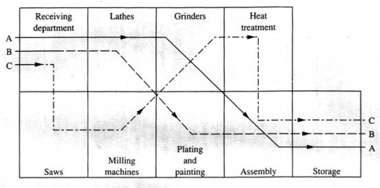
This type is characterized by large varieties of components, general-purpose machines, and a functional layout. This means that machines are collected by function (all lathes together, all milling machines together, etc.) and the parts are routed around the shop in small quantities to various machines.
Job Shop manufacturing is commonly done to specific customer orders, but in truth many job shops produce to fill finished goods inventories. Because different types of general purpose manufacturing equipment is used workers must have relatively high skill levels to perform a range of different work assignments. Job shop products include space vehicles, aircraft, machine tools, special tools, and equipment.

The main advantage of this layout is its ability to make a wide variety of products. Each different part requiring its own unique sequence of operations can be routed through the respective departments in the proper order. Route sheets are used to control the movement of the material. Forklifts and handcarts are used to move materials from one machine to the next.

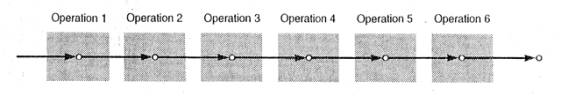
The flow shop has a product-oriented layout. When the volume gets very large it is called mass production. This layout can handle very large production rates. Computers, cars and washing machines are examples of products made by mass production. Specialized equipment is required. Dissimilar machines are grouped into a flow line and the entire plant is often designed exclusively for the production of the particular product. All the facilities are arranged according to the product’s sequence of operations and the line is organized by the processing sequence needed to make a single product or a regular mix of products.

A hybrid form of the flow line produces a batch of products (Batch Processing or Cellular Layout) moving through clusters of workstations or processes organized by product flow. The products are held in stock until they are needed to meet customer demand. There are three types of manufacturing cells:
1) Simple Cells, which are the generic application of cell principles and are very popular around the world.

2) Automated storage cells, because they utilize automated storage and retrieval system (ASRS) technology to accelerate flow.
3) Forced flow cells, as they are popular in Japan and emphasize machine utilisation.
In the typical project-manufacturing layout, a product must remain in a fixed position or location during manufacturing because of its size and/or weight. The materials, machines, and people used in fabrication are brought to the site. Shipbuilding, large aircraft assembly or even construction of buildings and bridges use fixed position layout. When the job is completed the equipment is removed from the construction site. The project shop invariably has a job shop/flow shop-manufacturing layout making all the components for the large, complex project and thus has a functionalised production system.
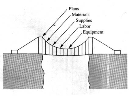
More generally a project is the type of process that makes a single unit, usually tailored to individual customer specifications. For example, building a Formula 1 car or writing a book are projects as well. These are the type of processes that people enjoy to work with in contrast with the flow shop processes where the work is often dull and monotonous.
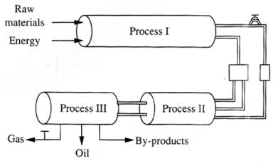
In the continuous flow processes, the product physically flows. Oil refineries, chemical processing plants, and food processing operations are examples. In continuous processes the products really do flow because they are liquids, gases or powders. Such processes use highly specialized equipment that can work for 24 hours a day without changes or interruptions. They are capital intensive, but they need a very small workforce and the high volume leads to low unit costs.
b)
Visit a manufacturing plant in your area or recall a past visit. What are
the parts and the products made at the plant? What type of Layout is used?
Sketch the layout of the facility indicating major manufacturing areas and
support facilities superimpose the flows of material on this layout. Do the
material flow pattern and layout seem well planned?
The Shipyard of Scaramanga is the largest shipyard in Greece, and it provides the facilities for building and repairing ships almost of all types and sizes (from small yachts to large oil tankers). It is possible to build and/or repair a large number of ships at the same time as well.
Shipbuilding involves a very large number of different processes and it is a characteristic example of a project shop layout. In most cases the ship’s engine is bought out finished (like many other parts), but in special cases it might be required to be manufactured, assembled and tested inside the shipyard. This process also uses a project shop layout.
Other parts of the ship are manufactured in workshops around the shipyard. Since each ship is build accordingly to customer’s specifications a large number of the parts required is unique. The layout of the workshops can be characterized by large varieties of components, general-purpose machines, and a functional layout. Machines are collected by function (all lathes together, all milling machines together, etc.).
The following picture shows a part of the Scaramanga shipyard.
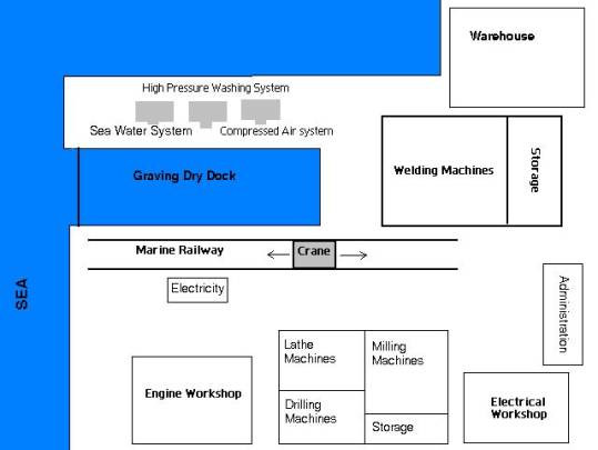
The Graving Dry Dock is the place where a ship is being built. Around the dock are all the workshops needed for manufacturing the parts of the ship. The layout of each workshop seems to be typical and well planned. However problems occur because of the lack of communication and information sharing between these workshops and between the workshops and the warehouse. A way to improve the information flow in the shipyard might be a computerized data communication system.
a)
Define Computer Integrated Manufacturing and list the steps, which a
company should take in implementing such a system.
Not universally accepted definition exists, but CIM is generally taken to imply computer assisted monitoring and control of all aspects of a manufacturing business, so providing a source of rapid information flow from which optimal operating decisions can be made.
CIM: The integration of design and production aspects of
manufacturing with traditionally separate areas such as planning, purchasing, data processing, financial
control, and management support. CIM has evolved out of earlier techniques such
as computer-aided design (CAD), computer-aided manufacture (CAM), numerical control of
machine-tools, robotics, flexible manufacturing
systems (FMS), and automated materials handling, all of which have been made
possible by the use of information technology and
computer-based systems. As a result of the programmability and flexibility of
the constituent processes, a CIM system can more easily be directed towards
optimising the effectiveness of the manufacturing operation as a whole, whereas
earlier approaches to manufacturing often had to concentrate on maintaining or
improving the efficiency of individual aspects only.
The steps that a company should take to implement a CIM system are the following:
1) Gain confidence in the CAD/CAM systems.
2) Increase programming confidence and capacity
3) Install a reliable Local Area Network (LAN).
4) Invest to computer hardware and software.
5) Reallocate jobs and responsibilities, and train workers.
b) Each student is required to submit the self assessment exercises on the following topics:
Q.1
Modern manufacturing processes began in the early 1800's. Eli Whitney's milling
machine was invented during which year?
Answer: 1818
Q.2 The
work of Fred W. Taylor gave a scientific basis to manufacturing, gets
credit as the origin of experimentation and analysis in manufacturing process.
What is the title of his published paper?
Answer: The art of cutting metal
Q.3
James Watts' steam engine was invented in 1776 began the industrial revolution.
This lead to the motive for seeking efficient source of power. Screw-cutting
lathes was invented in 1797 by Henry Maudsley. In what year was the kinematics
of the basic machine tools and structures for mechanical cutting methods
developed?
Answer: 1900
Q.4.
A manufacturing enterprise is a factory-based, profit-making organisation. Name
a common characteristic associated with profit making?
Answer: Willingness to assume risk
Process
planning
Q.1.
What is process planning?
Answer: 'The act of preparing detailed work instructions to produce a part'
Q.2.
Which of these functions is not a process planning activity?
Ø
The selection of machining
operations
Ø
The sequencing of
machining operations
Ø
Determination of set-up
requirement
Ø
Design the process plan
Ø
Jigs and fixtures design
Answer: Design the process plan
Q.3. Why is process planning necessary?
Answer: It is only necessary to transform an idea into a desired product part or component and to identify which machining processes and parameters are to be used.
Q.4. A cut is the sub-unit of an operation. It is a procedure in which the cutter passes the cutting surface once.
Answer: The above statement is True
Scheduling
Q.1.
Which of the below is a suitable scheduling system for a small-scale machining
shop?
Ø
Dispatching
Ø
Flow Scheduling
Ø Sequencing
Ø MRP
Answer: MRP
Q.2.
The anticipation of customer demand is a deciding factor in the choice of
scheduling technique for a manufacturer. True or false?
Answer: The above statement is True
Q.3. When scheduling manufacturing operations, which of the following should be an important consideration?
Ø
Product design
Ø
The safety of employees
Ø Trecyclability of components
Ø The available production capacity
Answer: The available production capacity
Q.4. Scheduling
is an activity carried out within what function of manufacturing?
Answer: Manufacturing planning
Q.1.
A form of organisation which involve setting up formal multifunctional teams, in
which lines of responsibility flow both horizontally and vertically is known
as.......................?
Answer: Matrix
Q.2. Financial management deals with efficient ............................. of both short- and long-term financial resources ?
Answer: Acquisition and deployment
Q.3. Financial management deals with efficient acquisition and deployment of both short- and long-term financial resources. Which of the following is not among the user group according to the Corporate Report 1975.
Ø
Minors
Ø
Equity investors group
Ø
Loan creditors
Ø
Employee group
Ø Analyst
Answer: Minors
Q.4. A market-focussed organisation makes decisions about .................................that clearly relate to the needs of the market.
Answer: Products and services
Q.1. Why was the OSI model created?
Answer: To identify all the tasks that might be needed in a communication process.
Q.2. What
does the OSI model describe?
Answer: The functions, which each layer must carry out.
c) Develop a layout of the Flexible Manufacturing Cell and explain the sequence of operations, which need to be performed in producing the chess pieces. Also describe your understanding of the following terms in relation to the Flexible Manufacturing cell, e.g. configurator, process planner, route planner, scheduler, and the role of the virtual reality in virtual manufacturing. Give examples and make use of figures where appropriate.
Layout and sequence of operations
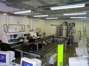
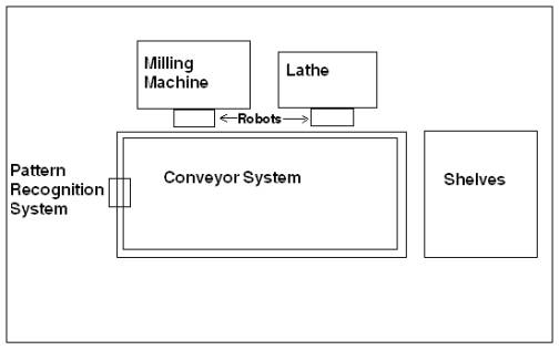
The sequence of operations is as follows:
Ø The blank piece is moved from the shelve and placed on the conveyor system
Ø Conveyor system starts moving
Ø Stops when the blank piece is in front of the Lathe
Ø The Robot places the piece inside the Lathe
Ø Lathe Guard closes and operation starts
Ø When operation finishes, lathe guard opens
Ø Robot places the piece back to the conveyor system
Ø Conveyor system starts moving
Ø Stops when the piece is in front of the milling machine
Ø The Robot places the piece inside the milling machine
Ø The Milling Machine’s guard closes and milling operation starts
Ø When operation finishes, milling guard opens
Ø Robot places the piece back to the conveyor system
Ø Conveyor system starts moving
Ø Stops when the piece is inside the pattern recognition system
Ø The piece is recognized (any manufacturing errors can be reported as well)
Ø Conveyor system starts moving again
Ø Stops when the recognized piece is in front of the shelves
Ø A robot places the chess piece on a predefined shelf depending on what kind of chess piece it is (Rook, Queen, King etc.).
The configurator module of the software is used for designing and
analysing a shop floor layout. Machine tools can be chosen, moved into place and
then given a name and characteristics. The shop floor can be re-designed to suit
the particular machine tool installation, or made up to show a completely
simulated factory.
When the shop floor layout is completed, the user may calculate the cellular structure of the shop floor. The software groups machine tools into autonomous cells and displays the result to the user. These cells may be altered according to the user’s needs. A further analysis tool can be used to show the connectivity of the machine tools on the shop floor. A Transportation Network can be created which shows how material is moved about the shop floor.
The Process Planner is simply a documentation tool, used to describe the functions necessary to produce a component. It aids in the creation of a component database Each component has a unique name, an identification number and several other properties defined by the process plan; the machining and measurement requirements are listed together with timing information and all tooling and work-holding data.
The route
planner is an application that automatically generates, or allows the user to
create, a route for a component around a shop floor. The shop floor must contain
the machine tools necessary to produce the component, together with suitable
material handling and storage devices. The user may determine the route for a
component around the shop floor, but the Route Planner assists by inferring
machine sequences and preventing impossible machine transfers.
The function of the dispatcher is to control the set of cells during
production. It executes the schedule by dispatching work-orders and
constantly monitoring the cells for BUSY and IDLE messages. The schedule is
updated as events, such as processes starting and finishing, occur on the shop
floor. The main screen shows the Gantt chart of processes scheduled in time
produced from the scheduling module. A line representing the current time moves
across the screen and the schedule is recalculated every second. If a process
runs late or finishes early, the other processes in the schedule are altered
accordingly. A detailed journal of events is recorded for analysis later. The
dispatcher also maintains a journal of status information and sends machine
information to the Configurator.
To manufacture a set of components a production
schedule has to be developed based upon the routes for the individual
components. The Bill of Processes is used for each component and its processes
are scheduled in time, ready for production. The scheduler is a part of the
software that takes into account the finite capacity of the machine tools and
ensures that a feasible schedule is produced. This schedule is displayed as a
colour-coded Gantt chart of processes. Each process has an estimated start-time
and end-time, based upon its position in the sequence and its duration.
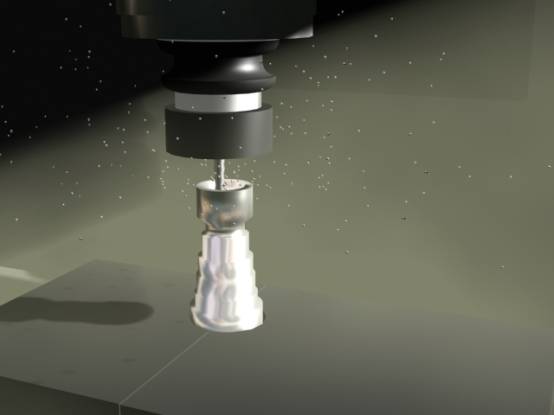
Virtual Reality can be seen as a
way for humans to visualize, manipulate and interact with computers and
extremely complex data.
Virtual Manufacturing is the use of a desktop virtual reality system for the computer-aided design of components and processes for manufacture. It offers unrivalled scope for creating and viewing three-dimensional engineering models, later to be passed to numerically controlled machines for real manufacturing.
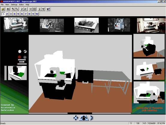
The following picture shows a model of the CIM centre and it was part of
my project (3D Visualization of CIM Centre using 3D Studio Max)
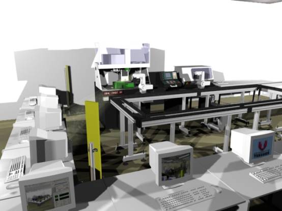
Some of the above models where imported into the virtual reality package Superscape VRT and a simple interface where made. In a Virtual reality package the environment is interactive, responding to and allowing itself to be modified by the user’s actions.
The following
picture shows an example.